VLSI DESIGN STYLES:
1 FIELD PROGRAMMABLE GATE ARRAY (FPGA) DESIGN:
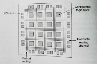
Field programmable gate array( FPGA) is a fully
fabricated IC chip in which the interconnections can be programmed to implement
different functions. An FPGA chip has thousands of logic gates which are to be connected
to be implement any logic function. A typical FPGA architecture is shown in
fig. It has the following three main components:
1. 1. I/O buffers
2. 2. Array of configurable logic
blocks(CLBs)
3.
3. Programmable interconnects.
In the FPGA- based design ,first a behavioural netlist
is written to describe the functionally of the design. This is done using the
hardware description languages such as Verilog or VHDL. Then the netlist is
synthesized to come up with the gate level design. The next step is to map the
logic blocks in to available lpgic cells. This progress is called the
technology – mapping. This is followed by placement and routine, which
configures the CLBs and defines interconnections. The next step is to generate
the bit -stream and download the bit -sream in to an FPGA chip with the help of
a software interface. Then the FPGA chip can function has desired as long as
the power is ON, or it is reprogrammed.
|
FPGA |
ASIS (APPLICATION
-SPECIFIC INTERGRATED CIRCUIT) |
|
Purchased from
vendor as a standarard part, then programmed by the user. |
Mae to customer
-specification by the vendor. |
|
No production set
-up costs ( fist unit costs the same as subsequent units) |
High production
set-up costs ( often in the $100,000range) |
|
Fast turn around
time ( can be programmed in a matter
of minutes) |
Slow turn around
time ( often at least 6 weeks) |
|
Relatively high
per unit cost and low capability per chip |
Lower per unit
cost-good for high volume production. |
|
Design requires
mostly writing HDL code (inVHDL or Verilog) |
Design often
requires knowledge of physical layout ofsilicon inside the IC |
TABLE:
COMPARISON BETWEEN FPGA AND ASIC
|
FPGA |
CPLD |
|
Performance
depend on the routing implemented for a particular application. |
Predictable
performance independent of internal placement and routine. |
|
Functionally
is implemented by lookup tables |
Functionally
is implemented by PAL-like structures |
|
Suitable
for medium t high density designs |
Suitable
for low to medium density design. |
|
More
complex and register – rich architecture. |
Regular
PAL-like architecture. |
|
Channel
– based interconnection fabric. |
Crossbar
type interconnection fabric. |
|
Can
be programmed as many times as possible. |
Can
be reprogrammed a limited number of times. |
TABLE:
COMARISON BETWEEN FPGA AND CPLD
2 GATE ARRAY
DESIGN:
In the gate array (GA)
structure, the transistors are fabricated on the silicon water. But the
interconnections are not fabricated. The metal mask layer are customized to
define the interconnections between the
transistors for a targated functionally. It can also be used for the prototype
development in short time. Ranked after the FPGA. GA- based design time
typically varies from a few days to a few weeks.
3.Standard
cell – based design:
The standard cell – based
integrated circuit refers to a class of integrated circuits which uses the predesigned ,pre-tested, and pre-
characterized standard cells. The standard cells include basic gates (AND ,OR, NAND,
NOR, XOR ,XNOR ,NOT, etc), some mega cells ( such as multiplexer, full-adder,
decoder, etc.) sequential elements ( such as D flip-flop, scan-FF, flip-flop
with direct set/ reset/ clear inputs, registers, etc), input -output buffers (
I/O Cells), and some special cells, All these standard cells are designed ,
tested, and characterizes and put in a database which is known as a standard
cell library.
In the standard cell – based architecture, the
standard cells are placed in rows to build the integrated circuits chip.
However, this design style also include the already designed mega modules or
fixed blocks.
4: FULL – CUSTOM DESIGN:
In the full- custom design,
the designers to not use the pre- designed standard cell library. Instead ,
they design the entire chip from the scratch. As each and every part is
designed in this approach the chip are highly optimized for area ,
power and delay.
Hence , a full custom design
is always superior to any other design style . however, full-custom design
cycle time is higher compared to other design styles. Full – custom design
style is used for high performance and
high volume products.
5: SEMI
CUSTOM DESIGN:
In this style of design , all
most all the basic building block are used from the standard cells liabrary.
Only few cells are designed from the begning, which are not available in this
standard cell liabrary or to be optimized for a specific target. The approach
is faster compare to full- custom style
but slower than the standard cell base design. Performance -wise also, it is
superior to the standard cell – based design but inferior to the full custom
designed
6
PROGRAMMABLE LOGIC DEVICE ( PLD):
Programmable logic device
(PLDs) are standard products, which can be programmed to optained the desire
functionality required for a specific application . the programing can be
either by the end user or by the manufacturer. The PLDs which are programed by
the manufacturer are known as mask- programmable logic device ( MPLDs) . the
PLDs , which are programed by end user are called field – programmable logic
device (PLDs) . the architecture of PLDs is very regular an fixe .It can not be
changed ny the end user. The PLDs having wide range of application and have
lo risk and cost in manufacturing in
large volume. Hence, the PLDs are chipper. As the PLDs are remanufactured ,
tested, and placed in inventory in andvance, the design cycle time is very
short. The PLDs are classified as 3 chatagories based on architecture and
programe ability.
1: read only memory ( ROM)
2: programmable array logic
(PAL)
3:PROGRAMMABLE LOGIC ARRAY (
PLA)


Great work!
ReplyDeleteVery well explained
ReplyDeleteGreat work!!
ReplyDeleteGreat work !
ReplyDeleteThank you
DeleteVery helpful for someone interested in VLSI.
ReplyDeleteThank you for appreciation and coming days we publish more blog related to these please do read that also
DeleteInformative 👍
ReplyDeleteNice work 👍
ReplyDeleteVery helpful nd descriptive blog keep it up
ReplyDeleteGood read
ReplyDeleteGood job
ReplyDeleteAmazinggg!
ReplyDeleteGreat work!
ReplyDeleteThanks for the appreciation
DeleteInformative!!
ReplyDeleteKeep it up...
Thanks for the appreciation
DeleteInsightful blog
ReplyDeleteThank you
DeleteHighly informative!
ReplyDelete👌🏻👍🏻
ReplyDelete👌🏻👍🏻
ReplyDeleteVery informative
ReplyDeleteWorth! A good read
ReplyDeleteThanks for the appreciation
DeleteMake read of our other blog also
Great job����
ReplyDeleteThanks and please check our other published blog also
DeleteVery informative
ReplyDeleteSuperb🔥🔥
ReplyDeleteThank you 😊😊
DeleteVery Nice!
ReplyDeleteThank you
DeleteWow ,very well written.
ReplyDeleteGreat!!!
ReplyDeleteGood content
ReplyDeleteGood work
ReplyDeleteGreat work!
ReplyDeleteThank you for appreciation
DeleteGood job
ReplyDeleteNice work!! 💯👍
ReplyDeleteThanks for the appreciation.
DeleteThank you
ReplyDeleteNicely Written 👍
ReplyDeletePlease read our other publish blog they also informative
ReplyDeletegreat work!!
ReplyDeleteGood Work
ReplyDeleteThank you ☺️☺️
DeleteThank you for appreciation
ReplyDeleteThank you and please do read our other blog also
ReplyDeleteGreat work!!
ReplyDeleteInformative 👍🏻
ReplyDeletegood survey,very informative
ReplyDeleteWell explained
ReplyDelete